Download Now on Google PlayStore
Kindly Click and View the Online Advertisements while reading the contents around this blog to motivate us to keep continuing the blog updated

Thursday, November 7, 2019

ET Lesson No 9: Resistance

ET Lesson No 9: Resistance

Definition of Resistance

The property of a substance to resist the flow of current through it is called resistance.

When a voltage is applied across a substance there will be an electric current through it. The applied voltage across the substance is directly proportional to the current through it. The constant of proportionality is resistance. Hence resistance is defined as the ratio of the applied voltage to the current through the substance.

Where V is voltage, I is current and R is resistance.

Concept of Resistance

To understand the matter let us take examples of metallic substances. There are numbers of free electrons moving randomly in the crystal structure of a metallic substance. When a voltage is applied across the resistance due to the electric field the free electrons drift from lower potential point to higher potential point in the substance. During drifting motion, the free electrons continually collide with atoms of the substance and this phenomenon prevents the free motion of electrons and this causes resistance.

Unit of Resistance

From the definition of resistance, it can be said that the unit of electric resistance is volt per ampere. One unit of resistance is such a resistance which causes 1 ampere current to flow through it when 1 volt potential difference is applied across the resistance. The unit of electric resistance that is volt per ampere is called ohm(Ω) after the name of great German physicist George Simon Ohm.

He is famous for his law called Ohm’s law which is applicable only on pure resistance. The unit ohm is normally used for moderate values of resistance but there may be a very large as well as a very small value of resistance used for different purposes. These values are expressed in giga-ohm, mega ohm, kilo-ohm, milli-ohm, micro-ohm even in nano-ohm range depending on the value of resistance.

Unit NameAbbreviationValue in ohm (Ω)
Giga OhmG Ω109 Ω
Mega OhmM Ω106 Ω
Kilo OhmK Ω103 Ω
Milli Ohmm Ω10 – 3 Ω
Micro Ohmμ Ω10 – 6 Ω
Nano Ohmn Ω10 – 9 Ω


Resistance of Different Materials

Depending on the resistance value substances are divided into three categories.

There are some materials mainly metallic substances that offer very low resistance to the current through them. These substances are referred to as conductors more precisely electrical conductors. Silver is an extremely good conductor of electricity but it is not widely used in electrical systems because of its high cost. Aluminum is a good conductor and it is a commonly used conductor because of its low cost and plenty of availability. Copper is another good conductor commonly used in different electronics and electrical circuits and it is a better conductor than aluminum but at the same time, it is costlier than aluminum.

There is another category of materials called semiconductors. These have a moderate value of resistance i.e. not very high as well as not very low at room temperature. There are endless uses of semiconductors for making electrons devices. Silicon, germanium are two mostly used semiconductor materials. In addition to these different compounds also behave as semiconductors.
The materials offer extreme resistance to the current is known as the insulator or electrical insulation material. These materials are a very bad conductor of electricity and mainly used to prevent leakage current in electric systems. Papers, dry woods, mica, porcelain, glass epoxy polyester, mineral oil, SF6 gas, Nitrogen gas, other gases, air, etc are very good examples of insulation materials.
Effect of Temperature on Resistance


In metallic substances with rising temperature the interatomic vibrations increase and hence offer more resistance to the movement of electrons causing the current. Hence, with increasing temperature the resistance of metallic substances increases. The temperature coefficient of resistance is positive for these materials. In semiconductors with increasing temperature the number of free electrons increases as at higher temperature more number of covalent bonds gets broken to contribute free electrons in the substance. This reduces the resistance of the substance. Hence semiconductors have a negative temperature coefficient of resistance.There are some materials mainly metals, such as silver, copper, aluminum, which have plenty of free electrons. Hence this type of materials can conduct current easily that means they are least resistive. But the resistivity of these materials is highly dependable upon their temperature. Generally metals offer more electrical resistance if temperature is increased. On the other hand the resistance offered by a non-metallic substance normally decreases with increase of temperature.
Resistance Variation With Temperature

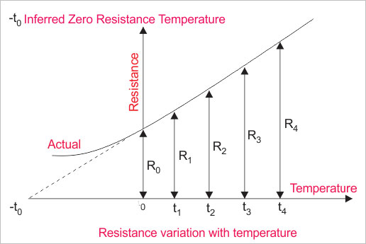
If we take a piece of pure metal and make its temperature 0' by means of ice and then increase its temperature from gradually from 0'C to to 100'C by heating it.

During increasing of temperature if we take its resistance at a regular interval, we will find that electrical resistance of the metal piece is gradually increased with increase in temperature. If we plot the resistance variation with temperature i.e. resistance Vs temperature graph, we will get a straight line as shown in the figure below. If this straight line is extended behind the resistance axis, it will cut the temperature axis at some temperature, – t0 'C. From the graph it is clear that, at this temperature the electrical resistance of the metal becomes zero. This temperature is referred as inferred zero resistance temperature.

Although zero resistance of any substance cannot be possible practically. Actually rate of resistance variation with temperature is not constant throughout all range of temperature. Actual graph is also shown in the figure below.

Let’s R1 and R2 are the measured resistances at temperature t1'C and t2'C respectively. Then we can write the equation below,

From the above equation we can calculate resistance of any material at different temperature. Suppose we have measured resistance of a metal at t1'C and this is R1.

If we know the inferred zero resistance temperature i.e. t0 of that particular metal, then we can easily calculate any unknown resistance R2 at any temperature t2'C from the above equation.

The resistance variation with temperature is often used for determining temperature variation of any electrical machine. For example, in temperature rise test of transformer, for determining winding temperature rise, the above equation is applied. This is impossible to access winding inside the an electrical power transformer insulation system for measurement of temperature but we are lucky enough that we have resistance variation with temperature graph in our hand. After measuring electrical resistance of the winding both at the beginning and end of the test run of the transformer, we can easily determine the temperature rise in the transformer winding during test run.

20'C is adopted as standard reference temperature for mentioning resistance. That means if we say resistance of any substance is 20Ω that means this resistance is measured at the temperature of 20'C.

Resistivity or Coefficient of Resistance

Resistivity or Coefficient of Resistance is a property of substance, due to which the substance offers opposition to the flow of current through it. Resistivity or Coefficient of Resistance of any substance can easily be calculated from the formula derived from Laws of Resistance.

Laws of Resistance

The resistance of any substance depends on the following factors,
  1. Length of the substance.
  2. Cross sectional area of the substance.
  3. The nature of material of the substance.
  4. Temperature of the substance.
There are mainly four (4) laws of resistance from which the resistivity or specific resistance of any substance can easily be determined.

First Law of Resistivity

The resistance of a substance is directly proportional to the length of the substance. electrical resistance R of a substance is

Where L is the length of the substance.

If the length of a substance is increased, the path traveled by the electrons is also increased. If electrons travel long, they collide more and consequently the number of electrons passing through the substance becomes less; hence current through the substance is reduced. In other words, the resistance of the substance increases with the increasing length of the substance. This relation is also linear.

Second Law of Resistivity

The resistance of a substance is inversely proportional to the cross-sectional area of the substance. Electrical resistance R of a substance is


Where A is the cross-sectional area of the substance.
The current through any substance depends on the numbers of electrons pass through a cross-section of substance per unit time. So, if the cross section of any substance is larger then more electrons can cross the cross section. Passing of more electrons through a cross-section per unit time causes more current through the substance. For fixed voltage, more current means less electrical resistance and this relation is linear.

Resistivity

Combining these two laws we get,


Where ρ (rho) is the proportionality constant and known as resistivity or specific resistance of the material of the conductor or substance. Now if we put, L = 1 and A = 1 in the equation, we get, R = ρ. That means resistance of a material of unit length having unit cross – sectional area is equal to its resistivity or specific resistance. Resistivity of a material can alternatively be defined as the electrical resistance between opposite faces of a cube of unit volume of that material.
Resistivity

Third Law of Resistivity     

The resistance of a substance is directly proportional to the resistivity of the materials by which the substance is made. The resistivity of all materials is not the same. It depends on the number of free electrons, and size of the atoms of the materials, types of bonding in the materials and many other factors of the material structures. If the resistivity of a material is high, the resistance offered by the substance made by this material is high and vice versa. This relation is also linear.
Fourth Law of Resistivity

The temperature of the substance also affects the resistance offered by the substance. This is because, the heat energy causes more inter-atomic vibration in the metal, and hence electrons get more obstruction during drifting from lower potential end to higher potential end. Hence, in metallic substance, resistance increases with increasing temperature. If the substance in nonmetallic, with increasing temperature, the more covalent bonds are broken, these cause more free electrons in the material. Hence, resistance is decreased with increase in temperature.

That is why mentioning resistance of any substance without mentioning its temperature is meaningless.

Unit of Resistivity

The unit of resistivity can be easily determined form its equation
The unit of resistivity is Ω – m in MKS system and Ω – cm in CGS system and 1 Ω – m = 100 Ω – cm.

List of Resistivity of Different Commonly Used Materials


MaterialsResistivity in μ Ω – cm at 20oC
Aluminium2.82
Brass6 to 8
Carbon3k to 7k
Constantan49
Copper1.72
Gold2.44
Iron12.0
Lead22.0
Manganin42 to 74
Mercury96
Nickel7.8
Silver1.6
Tungsten5.51
Zinc6.3
More than one electrical resistance can be connected either in series or in parallel in addition to that, more than two resistances can also be connected in combination of series and parallel both. Here we will discuss mainly about series and parallel combination.

Resistances in Series

Suppose you have three different types of resistors – R1, R2 and R3 – and you connect them end to end as shown in the figure below, then it would be referred as resistances in series. In case of series connection, the equivalent resistance of the combination, is sum of these three electrical resistances.

That means, resistance between point A and D in the figure below, is equal to the sum of three individual resistances. The current enters in to the point A of the combination, will also leave from point D as there is no other parallel path provided in the circuit.

Now say this current is I. So this current I will pass through the resistance R1, R2 and R3. Applying Ohm’s law, it can be found that voltage drops across the resistances will be V1 = IR1, V2 = IR2 and V3 = IR3. Now, if the total voltage applied across the combination of resistances in series, is V.

Then obviously

Series Resistors

Since, sum of voltage drops across the individual resistance is nothing but the equal to applied voltage across the combination.

Now, if we consider the total combination of resistances as a single resistor of electric resistance value R, then according to Ohm’s law,

V = IR ………….(2)

Series Resistor 1

Now, comparing equation (1) and (2), we get
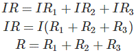
So, the above proof shows that equivalent resistance of a combination of resistances in series is equal to the sum of individual resistance. If there were n number of resistances instead of three resistances, the equivalent resistance will be



Resistances in Parallel

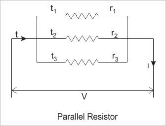
Say we have three resistors of resistance value R1, R2 and R3. These resistors are connected in such a manner that the right and left side terminal of each resistor is connected together, as shown in the figure below.
parallel-resistor

This combination is called resistances in parallel. If electric potential difference is applied across this combination, then it will draw a current I (say).

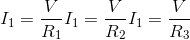
As this current will get three parallel paths through these three electrical resistances, the current will be divided into three parts. Say currents I1, I1 and I1 pass through resistor R1, R2 and R3 respectively.

Where total source current

Now, as from the figure it is clear that, each of the resistances in parallel, is connected across the same voltage source, the voltage drops across each resistor is the same, and it is same as supply voltage V (say).

Hence, according to Ohm’s law,

Now, if we consider the equivalent resistance of the combination is R.

Then,



Now putting the values of I, I1, I2 and I3 in equation (1) we get,


The above expression represents equivalent resistance of resistor in parallel. If there were n number of resistances connected in parallel, instead of three resistances, the expression of equivalent resistance would be

Let us take a conductor having a resistance of R0 at 0oC and Rt at toC respectively.
From the equation of resistance variation with temperature we get
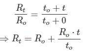
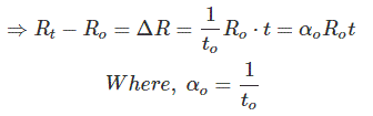
This αo is called temperature coefficient of resistance of that substance at 0oC.

From the above equation, it is clear that the change in electrical resistance of any substance due to temperature mainly depends upon three factors –

  1. the value of resistance at initial temperature,
  2. the rise of temperature and
  3. the temperature coefficient of resistance αo.

LEARN PLC Programming From A To Z

Wednesday, November 6, 2019

ET Lesson No 8: Electric Power, Electricity, Power Generation, Transmission and Distribution

ET Lesson No 8: Electric Power, Electricity, Power Generation, Transmission and DistributionElectric Power

Electric Power

Voltage and current are two basic parameters of an electric circuit. But, only voltage and current are not sufficient to express the behavior of an electric circuit element. We essentially need to know, how much electric power, a circuit element can handle. All of us have seen that a 60 watts electric lamp gives less light than a 100 watts electric lamp. When we pay electric bill for electricity consumption, we are actually paying the charges for electric power for a specified period of time. Thus electric power calculation is quite essential for analyzing an electric circuit or network.

Power is the rate of energy supplied or consumed by an electric element with respect to time

Suppose, an element supplies or consumes an energy of dw joules for a time of dt second, then power of the element can be represented as,
This equation can also be rewritten as,

Hence, as the expression of voltage and current in the equation are instantaneous, the power is also instantaneous. The expressed power is time-varying.
So, the power of a circuit element is the product of voltage across the element and current through it.


As we have already told that a circuit element can either absorb or deliver power. We represent the absorption of power by putting a positive sign (+) in the expression of power. Likewise, we put a negative sign (-) when we represent the power delivered by the circuit element. Passive Sign Convention
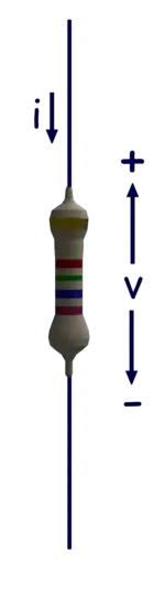
There is a simple relationship between the direction of current, polarity of voltage and sign of the power of a circuit element. We call this simple relationship as passive sign convention. When a current enters in an element through its terminal of positive voltage polarity, we put a positive sign (+) before the product of the voltage and current. This implies that the element absorbs or consumes power from the electric circuit. On the other hand, when the current through the element leaves its terminal of positive voltage polarity, we put a negative sign (-) before the product of the voltage and current. This implies that the element delivers or supplies power to the electric circuit. Let us take a resistor connected across two circuit terminals. Although, the rest of the circuit is not shown here in the figure. The polarity of the voltage drop across the resistor and the direction of current through the resistor are shown in the figure below. The resistor is consuming power of vi watts as current i ampere enters in the resistor though its positive side of the dropped voltage v volt, as shown.
resistor
Let us take a battery connected across two circuit terminals. Although, the rest of the circuit is not shown here in the figure. The polarity of the voltage drop across the battery and the direction of current through the battery are shown in the figure below. The battery is delivering a power of vi watts as current i ampere enters in the battery of v volt through its positive polarity terminal as shown.
battery

Electricity

There are some inventions which charged the human civilization. The first invention was the wheel, the second invention was electricity, the third invention was telecommunication, and the fourth invention was the computer. We will discuss here the basic introduction of electricity. Each substance in this universe is made of plenty of atoms and each atom has the same number of negative electrons and positive protons. As a result, we can say that each neutral substance has the same number of electrons and protons in it. The protons are immovable and strongly attached to the nucleus of the atoms. Electrons are also bounded to atoms and orbiting around the nucleus in different distinct levels. But some of the electrons can move freely or can come out from their orbit due to external influences. These free and as well as loosely bonded electrons cause electricity.

In a neutral condition, the number of electrons and protons is the same in any piece of substance. But if somehow the number of electrons in a substance becomes more than the number of protons, the substance becomes negatively charged as the net charge of each electron is negative. If the number of electrons in a substance becomes less than the number of protons, the substance becomes positively charged.The concentration of free electrons always tries to be uniform. This is the only reason for electricity. Let us explain in detail. If two dissimilarly charged conductive bodies come in contact, the electrons from the body of higher electron concentration will move to the body of lower electron concentration to balance the electron concentration of both bodies. This movement of charge (as electrons are charged particles) is electricity.

The related terms in electricity

Electric Charge: 

As we told earlier that the number of electrons and number of protons are equal in a neutral body. The amount of negative charge and positive change is also equal in a neutral body since the electric charge of an electron and a proton is numerically equal but their polarity is opposite. But for any reason, the balance of the number of electrons and protons in a body gets distributed the body becomes electrically charged. If the number of electrons more than that of protons the body becomes negatively charged and the amount of charge depends on the number of excess electrons in the body. In the same manner, we can explain the positive change of a body. Here the number of electrons becomes lesser than that of protons. The positivity of the body depends on the difference between protons and electrons in the body.

Electric Current: 

When charge flows from one point to another to make uniform charge distribution then the rate at which the charge is flowing called electric current. This rate mainly depends on the difference between the charged condition of two points and the conditions of the pathway through which the charge is flowing. The unit of electric current is Ampere and it is nothing but coulomb per second.

Electric Potential: 

The level of the charged condition of a body is known as electric potential. When a body is charged it gets the ability to do some work. Electric potential is the measurement of the ability of a charged body to do work. The current flowing through a conductor is directly proportional to the difference of electric potential between at two ends of the conductor. The electric potential can be visualized as the difference of water level in two water tanks linked with a pipeline. The speed of water flowing from the higher headed tank to lower headed tank depends on the level difference or head difference of the water in the tanks not on the quantity of water stored in the tanks. In the same way, the electric current between two bodies depends on the potential difference between two bodies not on the quantity of charge stored in the bodies.

Electric Field: 

There is always a force between two nearly placed charged bodies. The force may be either attractive or repulsive depending on the nature of the charge of two bodies. When a charged body enters the nearby zone of another charged body the force is practically experienced. Space surrounds a charged body where another charged body can experience a force is called the electric field of the former body.
These above mentioned four terms are the main parameters of electricity.

How is Electricity Generated

There are three basic ways by which we generally produce electricity.

Electromechanical Process: 

When a conductor moves in a magnetic field and the conductor cuts the field flux lines electricity is produced in the conductor. Depending on this principle all electrical generators work such as DC generators, alternators, and all kinds of dynamos.

Electrochemical Process:

In all types of battery electricity is produced due to chemical reactions. Here chemical energy gets converted to electrical energy.

Solid State Electric Generation: 

This is the most modern process of electricity generation. Here, free electrons and holes are generated at a PN junction and distribution of charge carriers gets imbalanced across the PN junction when the junction is exposed in the light. These free electrons and holes and their imbalanced distribution across the junction cause electricity in an external circuit. On this principle, PV solar cells work.

Types of Electricity

When electricity produced in the armature of a generator it is always alternating. That means polarity of electricity alters in a periodic interval. In DC generators the produced electricity in armature gets rectified through commutator. In alternators, the AC produced in the armature supplied to the external circuit through slip rings.
When electricity does not change its direction it is called DC electricity. Batteries and solar cells produce DC electricity.

Generation Transmission and Distribution of Electricity

After electricity gets generated in an electrical power plant it gets stepped up by step up transformer for transmitting purpose. Generation of electricity at low voltage level is practical and economical. But low voltage transmission is not economical. But for electrical transmission, the generated electricity first gets stepped up and then after transmission it is stepped down by step down transformers for electrical distribution purpose. Generation of electricity, transmission of electricity and distribution of electricity are normally with three phase system. Very ultra high voltage ac transmission is not economical always and that is why dc transmission is sometimes used. The supply system of domestic houses may be a single phase AC but all commercial, industrial and bigger house supplies are of three phase system.

Distribution of Electricity


Nature of Electricity and Concept of Electricity

Electricity is the most common form of energy. Electricity is used for various applications such as lighting, transportation, cooking, communication, production of various goods in factories and much more. None of us exactly know that what is electricity. The concept of electricity and theories behind it, can be developed by observing its different behaviors. For observing nature of electricity, it is necessary to study the structure of matters. Every substance in this universe is made up of extremely small particles known as molecules. The molecule is the smallest particle of a substance into which all the identities of that substance are present. The molecules are made up of further smaller particles known as atoms. An atom is the smallest particle of an element that can exist.

There are two types of substances. The substance, that’s molecules are made of similar atoms is known as an element. The matter whose molecules consisting dissimilar atoms, is called a compound. The concept of electricity can be achieved from the atomic structures of substances.An atom consists of one central nucleus. The nucleus is made up of positive protons and charge less neutrons. This nucleus is surrounded by numbers of orbital electrons. Each electron has a negative charge of – 1.602 × 10 ^ – 19 Coulomb and each proton in the nucleus has a positive charge of +1.602 × 10 ^ – 19 Coulomb. Because of the opposite charge there is some attraction force between the nucleus and orbiting electrons. Electrons have relatively negligible mass compared to the mass of the nucleus. The mass of each proton and neutrons is 1840 times the mass of an electron.

As the modulus value of each electron and each proton are same, the number of electrons is equal to the number protons in an electrically neutral atom. An atom becomes positively charged ion when it loses electrons and similarly an atom becomes negative ion when it gains electrons.

Nature of Electricity

Atoms may have loosely bonded electrons in their outermost orbits. These electrons require a very small amount of energy to detach themselves from their parent atoms. These electrons are referred as free electrons which move randomly inside the substance and transferred from one atom to another. Any piece of substances which as a whole contains an unequal number of electrons and protons is referred as electrically charged. When there is more number of electrons compared to its protons, the substance is said to be negatively charged and when there is more number of protons compared to electrons, the substance is said to be positively charged.

The basic nature of electricity is, whenever a negatively charged body is connected to a positively charged body by means of a conductor, the excess electrons of negative body starts flowing towards the positive body to compensate the lack of electrons in that positive body.Hope you got the very basic concept of electricity from the above explanation. There are some materials which have plenty of free electrons at normal room temperature. Very well known examples of this type of materials are, silver, copper, aluminium, zinc etc. The movement of these free electrons can easily be directed to a particular direction if the electrical potential difference is applied across the piece of these materials. Because of plenty of free electrons these materials have good electrical conductivity. These materials are referred as good conductor. The drift of electrons in a conductor in one direction is known as the current. Actually electrons flow from lower potential (-Ve) to higher potential (+Ve) but the general conventional direction of current has been considered as the highest potential point to lower potential point, so the conventional direction of current has been just opposite of the direction of flow of electrons. In non-metallic materials, such as glass, mica, slate, porcelain, the outermost orbit is completed and there is almost no chance of loosing electrons from its outermost shell. Hence there is hardly any free electron present in this type of material.

Hence, these materials cannot conduct electricity in other words electrical conductivity of these materials is very poor. Such material are known as non-conductor or electrical insulator. The nature of electricity is to flow through a conductor while an electrical potential difference applied across it, but not to flow through insulator even high electrical potential difference applied across them.


ET Lesson No 7: Sinusoidal Wave Signal & Electric Power in AC Circuit

ET Lesson No 7: Sinusoidal Wave Signal & Electric Power in AC Circuit


What is the Signal?

There are different measurable quantities in the world surrounding us. Some quantities are constant like acceleration due to gravity, speed of light, velocity of sound in air. Some are time-varying like AC voltage, Pressure, Temperature. It means they change their value as time passes on. Signal simply means the value of any quantity taken over a period of time. Signals are usually time varying in nature. Generally a graph is plotted between values at different time instants. This is called graphical representation of signal.

What is Sine Wave or Sinusoidal Wave Signal?

Sine Wave or Sinusoidal Wave Signal is a special type of signal. It is given by the function


When Sine wave starts from zero and covers positive values, reaches zero; and again covers negative values, reaches zero, it is said to have completed one cycle or single cycle.

The upper part of sine wave is called positive cycle and the lower part is called negative cycle in a single cycle.

For different values of time, the Signal gives the values of quantity at that time. Therefore Signal is a function of time. It is therefore written asf (t). The Maximum value of the Sinusoidal Signal is also called its amplitude (A). Here ω is called Angular Frequency of Signal and f is the Frequency of Signal. ∅ Is called Phase difference.

Frequency is measured in Hertz (Hz). It shows number of cycles of signal that took place in a second. Large ω or large f value indicates that the signal completes more oscillations (i.e., going from positive values to negative values) in less amount of time. Hence the Signal is more Oscillatory in nature.

Sinusoidal signal need not start at zero. It may start after certain duration of time. This is time after which Sinusoidal Signal starts is indicated with the help of phase difference (∅). It is measured in Radians.

Periodic signals are those which repeat their pattern after certain amount of time. This time after which pattern is repeated is called time period (T) of Periodic Signal. It is inverse of frequency of Signal.

A sinusoidal signal is a periodic signal, because the pattern keeps on repeating after one Wavelength as shown in the Figure above.

All the power signals in our home, office and industries are AC sinusoidal signals. The frequency (f) in India and British countries is 50 Hz and in American countries it is 60 Hz.

Why is Sinusoidal Wave Signal so Important?
Sinusoidal signals are important in both electrical and electronic engineering domains.

According to Fourier Series Theory, any signal (Periodic Signal) can be written in terms of only sine and cosine Signals of different frequencies. Therefore a complex signal can be broken-down into simple sine and cosine signals and mathematical analysis becomes easy. Hence it is widely used in electrical and electronic analysis.

Also, in transformers the output voltage is time derivative of magnetic flux. Magnetic flux is itself time derivative of input voltage. But we want same voltage signal both at input and output. The only functions that satisfy this condition are sine and cosine functions. As sine signal starts from zero value, it is preferred. Therefore majority of power systems in the world today are using sinusoidal AC voltage. All the household equipment also work on Sinusoidal AC voltage.

Power in AC Circuit

AC circuits are usually three-phase for electrical distribution and electrical transmission purposes. Single phase circuits are commonly used in our domestic supply system. The total power of a three-phase AC circuit is equal to three times the single phase power. So if the power in a single phase of a three-phase system is ‘P’, then the total power of the three-phase system would by 3P (provided the three-phase system is perfectly balanced). But if the three-phase system is not exactly balanced, then the total power of the system would be the sum of the power of individual phases. Suppose, in a three phase system, the power at R phase is PR , at Y phase is PY and at B phase is PB, then total power of the system would be
This is simple scalar sum, since power is a scalar quantity. This is the season, if we consider only single phase during calculating and analyzing of three phase power, it is enough.

Let us consider, network A is electrically connected with network B as shown in the figure below:
electrically connected network
Let us consider the expression of the voltage waveform of a single phase system is:

Where V is the amplitude of the waveform, ω is the angular velocity of propagation of the wave.Now, consider the current of the system is i(t) and this current has a phase difference from the voltage by an angle φ. That means current wave propagates with φ radiant lag in respect of the voltage. The voltage and current waveform can be represented graphically as shown below:
voltage waveform
The current waveform in this case can be represented as:
current voltage waveform
Now, the expression of the instantaneous power,
[where Vrms and Irms is the root mean square value of voltage and current waveform]Now, let us plot the term P versus time,
p versus time
It is seen from the graph that, the term P does not have any negative value. So, it will have a nonzero average value. It is sinusoidal with a frequency twice of system frequency. Let us now plot second term of the power equation, i.e. Q.
second term of power equation
This is purely sinusoidal and has a zero average value. So from of these two graphs, it is clear that P is the component of power in an AC circuit, which actually transported from network A to network B. This power is consumed in network B as electric power.

Q on the other hand does not really flow from network A to network B. Rather it oscillate between network A and B. This is also component of power, actually flowing into and out of the inductor, capacitor like energy storage elements of the network.

Here, P is known as the real or active part of the power and Q is known as imaginary or reactive part of the power

Hence, P is called real power or active power, and Q is called imaginary or active power. The unit of active power is Watt, whereas the unit of reactive power is Voltage Ampere Reactive or VAR.

We have already considered,
where, S is the product of root mean value of voltage and current i.e.
This product of RMS value of voltage and current of a system is referred as apparent power is Voltage Ampere or VA. So,
This can be represented in complex form as
Again, the expression of the real power is
where ɸ is the angle between voltage and current phasor. So,
So, here in the expression P, cos ɸ is the factor which determines the real power component of an apparent power S.

This is why the term cos ɸ in the expression of real power is called power factor. For both positive and negative value of ɸ, cos ɸ is always positive.


This implies, regardless of the sign of ɸ (which is dependent on whether the current is lagging or leading the voltage) real power is always positive.

That means it flows from the sending end (Network A) to the receiving end (Network B). We have also shown the same earlier when looking at the waveform for real power.

Now if the current is leading the voltage, then the angle between voltage and current phasor is negative, taking the voltage phasor as reference:

Voltage phasor
In that case, the reactive component of the power is negative,
Power Triangle

The relation between apparent power to active power and reactive power can be represented in trigonometric form as shown below.
power triangleNow, if the current is lagging the voltage the angle between voltage and current phasor is positive, taking the voltage phasor as reference.
In this case, the reactive component of power is positive. Since,
The power triangle is represented as shown below.
the power triangle
If the impedance of the network is capacitive, the current leads the voltage and in case of inductive network the current lags voltage. So we can conclude, the reactive power is negative in the case of capacitive reactance and it is positive and in the case of inductive reactance.

If the network is purely resistive, there would not be any angular difference between current and voltage. Hence,
So the reactive power, in this case, would be,
Thus, there is no reactive power generated or consumed in the network.